

In my previous post, I went into details on how to write a driver for the VL6180X. In this post, I want to continue by implementing a driver for another time-of-flight sensor from ST, the VL53L0X. I won't go into details about I2C in this post. Instead, I will re-use the I2C layer as for the VL6180X and only focus on the VL53L0X-specific parts.
As I began implementing the driver for VL53L0X, I quickly realized it was harder to get working than the VL6180X because it's a more complex and configurable sensor. On top of that, ST has focused on providing a "not-so-good" API driver instead of comprehensive documentation.
The quick route to get the VL53L0X working is to pull in the entire API driver from ST and only implement the lower I2C drivers specific to your microcontroller. The downside of this is that you have to include their bloaty (and potentially buggy) code, which is a problem if you are trying to minimize the memory footprint. Therefore, it's often preferable to implement your driver and only use the vendor code as a reference.
In this post, I will create a minimal driver to initialize and do a single range measurement with the VL53L0X. This will be helpful to those of you who are trying to write a custom driver for the VL53L0X. I will also add support for multiple VL53L0X, and give you some more information to help you tailor the VL53L0X for your application.
The code
All of the code is available at GitHub, and I also share parts of it as gists in this post. The easiest way to follow along is to pull down the repo from GitHub and then use interactive git rebase (git rebase -i --root) because I have basically made a new commit after each section.
About VL53L0X
The VL53L0X measures range by emitting light from a laser and measuring the light reflected back on its array of SPADs.
Like the VL6180X, the VL53L0X has a microcontroller on board, handling the computation and configuration, and interfaced with I2C.
It measures a range between ~0-2 meters at up to 50 Hz, but the exact performance depends on your configuration and operating conditions.
See ST's documentation for more details.
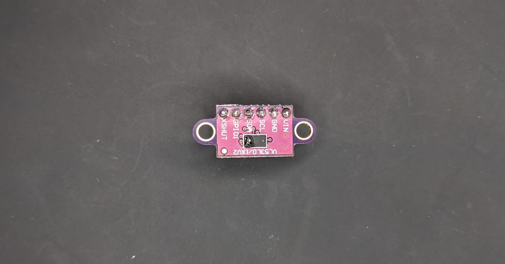
NOTE: Be careful when you solder the header pins, so you don't melt the sensor case as I've done in the image above.
How to hook up the VL53L0X
Just as in my previous post, I will use a VL53L0X breakout board and hook it up to a MSP430 LaunchPad. All the breakout boards that I've seen have the same pinout:
| Pin | Description |
|---|---|
| VIN | Support 5 V or 3.3 V (double-check your breakout board to make sure) |
| XSHUT (GPIO0) | Set sensor in reset (useful for multi-sensor support, otherwise can be left unconnected) |
| GPIO1 | Interrupt pin (can be left unconnected if polling) |
| GND | Ground |
| SDA | I2C data line |
| SCL | I2C clock line |
At minimum - when using a single sensor and no interrupt - you must connect four pins: SDA, SCL, VIN, and GND. My setup looks like this:
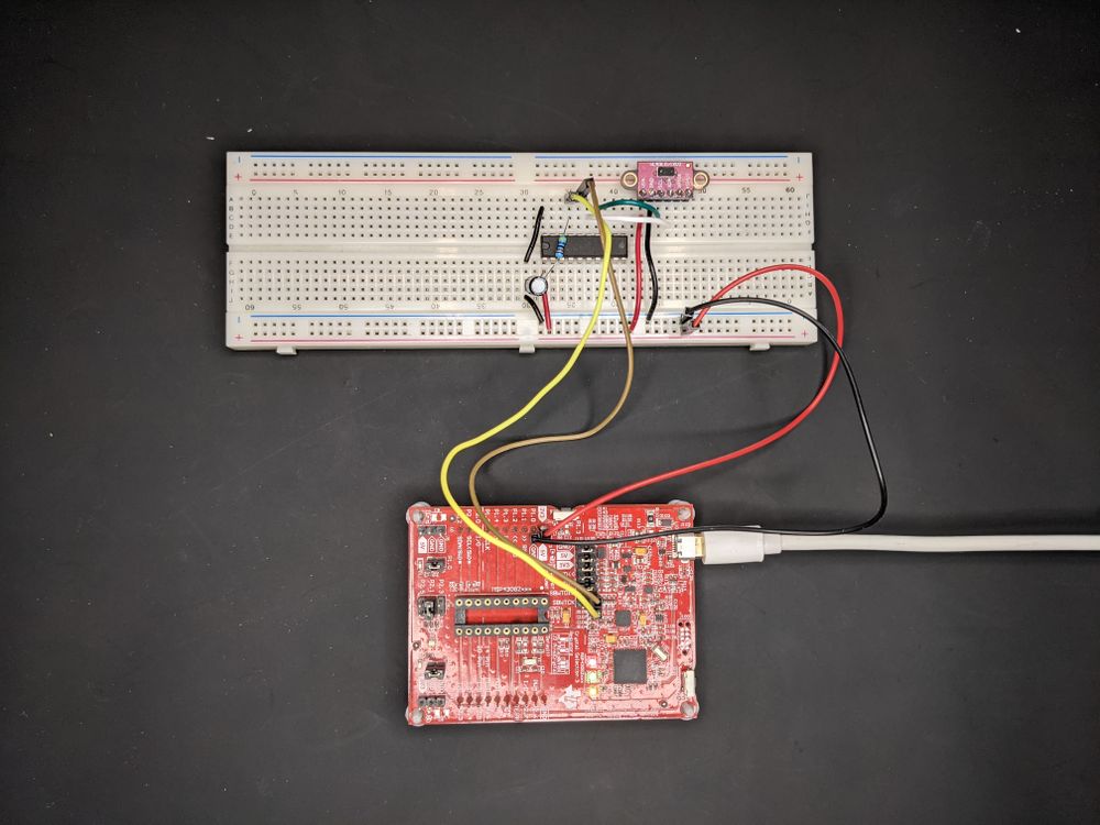
As you can see, I've moved the MSP430 DIP package from the launchpad to the solderless board. I find this makes the prototyping a bit cleaner. If you do this, don't forget to connect the reset pull-up resistor to stop the MSP430 from endlessly rebooting. You should also connect a bypass capacitor (~0.1 uF) to prevent the current surge from the VL53L0X from reseting the MSP430.
Tip: Verify the VL53L0X with an Arduino
There are several Arduino libraries for the VL53L0X, and they only take 5 minutes to set up. If you have an Arduino, please use it to sanity-check that your VL53L0X works before writing your own driver to avoid wasting time on a faulty sensor.
Verify the I2C communication
Building on top of the I2C driver from my previous post, we should create a function to verify that we can talk to the VL53L0X. The simplest way is to read a register with a known value. The datasheet suggests several registers:

The first one, 0xC0, contains the device model id, which is always 0xEE for VL53L0X. If we read the value 0xEE from this register, we know that the VL53L0X is up and that the I2C communication works.
Running in debug mode, you should see:

NOTE: The registers on the VL53L0X are 8-bit addressed (NOT 16-bit addressed as on the VL6180X). Make sure you use the 8-bit version of the I2C functions.
A minimal driver
The VL53L0X is a complex sensor with many configurable registers. I won't cover them all, instead, I aim to provide you with a minimal driver example that is capable of doing a single range measurement.
Since ST's documentation lacks vital information, I've had to study the code they provide as well as the library by Pololu, and after some trial and error extracted the necessary bits.
Similar to the VL6180X driver, I put all of the code for the VL53L0X driver in two files drivers/vl53l0x.h and drivers/vl53l0x.c.
How to initialize the VL53L0X
There are several steps to initialize the VL53L0X, and the datasheet provides an overview of them:

The necessary steps are device initialization and temperature calibration. We can skip the SPAD, Offset, and Crosstalk calibration for our minimal driver because the default values are good enough. These extra calibration steps are necessary when you use a cover glass. Though, you may want to do SPAD calibration later on even if you don't have a cover glass (for more info, see SPAD management).
Once again, it's helpful to define the registers at the top of the C file. ST unfortunately doesn't provide a complete register map for the VL53L0X, so instead, we have to extract the values from the code they provide.
Device initialization
The device initialization is divided into two steps, data initialization and static initialization.
Data initialization sets the voltage mode (1v8 or 2v8), the I2C mode (standard or fast), and retrieves the value for the stop variable. The stop variable is used for initiating the stop sequence when doing range measurement. It's not obvious why this stop variable exists.
I set the voltage mode to 2v8 because that's what my breakout board is designed for (and probably most others). I set the I2C mode to standard because the I2C driver is configured for standard mode (100 kHz).
Static initialization loads the default tuning settings, enables interrupt, and sets the sequence steps.
ST provides the default tuning settings (without explanation) in their API driver.
Interrupt settings are explained a bit more in section 6.8 of UM2039. Even if we are not using the interrupt pin, we must still enable interrupt to poll the interrupt register. I also configure the pin to be active low since my breakout board pulls the pin up by default. Lastly, we should ensure the interrupt is cleared.
The range measuring process is divided into a sequence of steps, and we should explicitly enable the steps we want to use. They have not explained in detail anywhere, but there are five of them:
| Sequence step | Description (my guess) |
|---|---|
| Minimum signal rate check (MSRC) | Check if the signal rate is below a certain threshold, return error value if it is |
| Target CentreCheck (TCC) | Check to see if the target is centered? |
| Dynamic SPAD selection (DSS) | Dynamically select the active SPADs to avoid saturating from too much light |
| Pre Range | First stage of range measuring (I don't know what it does) |
| Final Range | Second stage of range measuring (I don't know what it does) |
Following what ST does, I enable everything but MSRC and TCC.
And the full static_init function:
Temperature calibration
Apart from the basic initialization, we need to calibrate to compensate for temperature, which is explained in the datasheet:
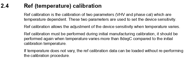
Glancing at the ST API driver once again, I created the corresponding code:
Finally, we should define the "public" init function, which calls all of the init functions we have defined.
After calling this function, the sensor is ready for range measuring.
For the complete code until this point, look at this commit.
Single range measurement
Once the sensor is initialized, it only takes a few lines of code to do a single range measurement. These are the steps:
- Stop any ongoing range measuring
- Trigger a new range measurement
- Wait for it to start
- Poll interrupt
- Read range
- Clear the interrupt
And in code:
The complete code until this point.
Multi-sensor support
We got a single sensor working, but let's also add multi-sensor support.
When using multiple VL53L0X on the same I2C bus, we have the same problem as with the VL6180X, we get bus collision because they share the same default I2C address. We solve it the same way: put all sensors in hardware standby and then power them up and configure their address individually. This solution is described in the application note AN4846.
How to hook up multiple VL53L0X
Besides connecting the sensors to the VCC, GND, SDA, and SCL pin, we should also connect the XSHUT (GPIO0) pin for hardware standby. I will be using three sensors as an example and connect their XSHUT to p1.0, p1.1 and p1.2 of the MSP430.

NOTE: Consider the pull-up resistance if you use many breakout boards. The effective resistance may become too low if you use many breakout boards, and you may need to desolder the pull-ups from some of them. Though three boards worked fine for me (~3.3 kOhm pull-up).
Modify the driver to support multiple sensors
The code is almost identical to VL6180X, so please read my other post for more details. One difference is that there is no "fresh out of reset" register, so we read the device id register instead. Another is that VL53L0X returns 8190 or 8191 when nothing is blocking them, but this is by default. Note, I'm not sure, but the limit checks may affect this return value (see Ranging profiles).
The new code (probably easier to study the commit on GitHub):
Additional notes
This post aimed to give you a minimal code example for VL53L0X. There is much more you can configure to better adapt the VL53L0X for you application. I won't go into everything, but I do want to talk about some of it in this section.
SPAD management
One thing that ST doesn't explain in detail is the configuration of the SPAD array.
The single-photon avalanche diodes (SPADs) array is the set of diodes that measures the reflected light that's emitted by the laser. The VL53L0X has 16x16 = 256 of them, but only a handful of them should be used to achieve a good signal rate. Exactly which SPADs to enable depends on the particular VL53L0X, operating conditions, and whether a cover glass is used or not.
During production, ST calibrates and generates a good reference SPAD map, which marks the best diodes (I think) among the 256 diodes. This map is different for each VL53L0X unit, and ST saves it to the non-volatile memory (NVM).
From what I've extracted, we basically have three options for configuring the SPADs:
Option 1: Do nothing: By default, the SPADs are enabled according to the good reference SPAD map
Option 2: Enable a subset of the good reference map: Only a subset of the good reference SPAD map should be enabled for optimal signal rate. ST also saves the number and type of SPADs to enable from the good reference SPAD map, which is based on the SPAD calibration they run in production. We can retrieve these values from NVM to reconfigure the SPAD map accordingly.
Option 3: Run SPAD management calibration: We can run the SPAD management calibration ourselves to determine the best SPADs to enable from the good reference SPAD map.
I quickly compared all three using a breakout board (no cover glass) and in relatively normal operating conditions. In my case, the difference is small, but option 2 gives slightly better readings than option 1, and option 3 slightly better than option 2. The difference is likely much more noticeable with a cover glass.
The code we have written so far relies on option 1. I will go ahead and also implement option 2, but then only discuss option 3.
SPADs
Before moving on, there are a few things you should know about the SPADs.
There are two types of SPADs, aperture and non-aperture, and only one type of SPAD should be enabled simultaneously. ST doesn't explain the difference between these two, but if it's related to the aperture concept of a digital camera, it probably means that the aperture SPADs are covered to capture less light.
In total, there are 16x16=256 SPADs divided into four quadrants where the third quadrant is non-aperture and the rest is aperture. And if I've interpreted ST's code right, we should only enable SPADs within an area of 44 SPADs. ST has also hardcoded the start of this area to the 180th diode, meaning the area only spans the third and fourth quadrant.
Option 2: Load SPAD config from NVM
To load the SPAD configuration from the NVM, we must set up the registers to read the data from NVM, and then create and write the SPAD configuration accordingly. We should do this as part of the static initialization.
Below I've extracted the required parts from the ST driver and tried to simplify it as much as possible:
NOTE: To save some lines of code, we can read the good reference SPAD map directly from the SPAD configuration register instead of from the NVM.
Option 3: Reference SPAD calibration
To get the best SPAD configuration, you should do SPAD calibration, which ST further explains:
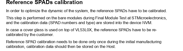
I won't implement it, but if you are interested, you should refer to VL53L0X_PerformRefSpadManagement in ST's API code. It takes some tedious code to get this working, so before you do, measure the difference with an Arduino first (Adafruit's library has support). You could also take a shortcut by extracting the resulting SPAD map using the Arduino and hard-code those values in your code.
NOTE: SPAD calibration doesn't produce a new reference SPAD map. It only finds an optimal subset of SPADs to activate from the good reference map already stored in the NVM.
NOTE: Every sensor unit is unique, so you must run the SPAD calibration for each sensor.
Ranging profiles
Apart from configuring the SPAD map, you can configure the VL53L0X with different ranging profiles for a trade-off between speed, accuracy, and range. ST provides four example profiles:
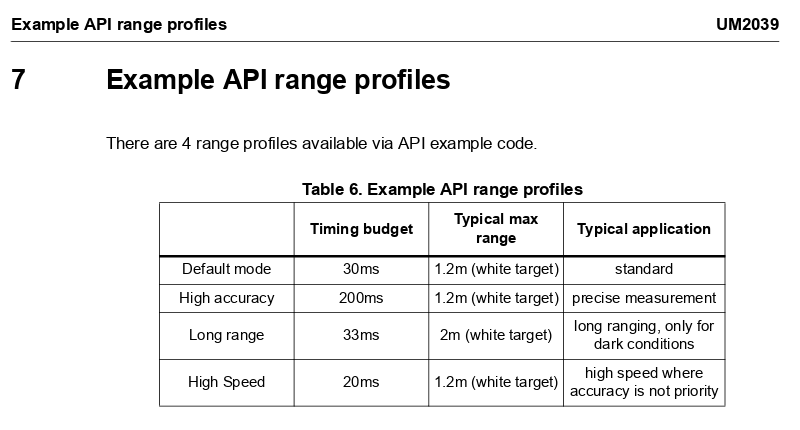
The API document explains what you need to do to configure each example profile. If you want something other than the default profile, you should read the API documentation and refer to these ST API functions:
VL53L0X_SetLimitCheckValue: Change the limit checks, i.e., longer range at the cost of more false positives
VL53L0X_SetMeasurementTiming BudgetMicroSeconds: Set the total time allowed for single range measurement, i.e., shorter time at the cost of accuracy.
VL53L0X_SetVcselPulsePeriod: Change the laser pulse period. A longer pulse period potentially gives a longer range.
Continuous (timed) mode
The VL53L0X can operate in two modes: single and continuous. In single mode, which we used in previous sections, we must start the range measuring each time. In continuos mode, range measurements run automatically one after another, immediately or with a set interval (intermeasurement period). If you want to use continuous mode you should refer to the following ST API functions:
VL53L0X_StartMeasurement()
VL53L0X_SetInterMeasurementPeriod MilliSeconds()
VL53L0X_GetInterMeasurementPeriod MilliSeconds()
Other things to look into
Improve initialization time: It's unnecessary to do the calibration each power-up. You can cut down startup time by saving the values to persistent memory
Interrupt: It's generally a good idea to wait for an interrupt rather than polling a register, especially if you configure the sensor to operate in continuous mode.
Error handling: I've kept error reporting to a bare minimum. You may want to report and handle errors better in your application.
Cover glass: If you use a cover glass, you must do the additional calibration.
Many sensors: A tip is to add a GPIO expander if you use many sensors and run out of pins on your microcontroller. You may also want to use different range profiles for the individual sensors.
Gesture recognition: VL53L0X is not only for range measurement, it also supports gesture recognition.
Recommended reading
First of all, have a look at the previous post.
The bulk of the documentation is to be found at ST's page for VL53L0X:
- User manual UM2039
- UM2039 API manual
- AN4846 Using multiple sensors
- A power point describing the technology in VL53L0X, VL6180X, and VL53L1X
Have a look at the Arduino libraries as well, especially the one from Pololu because it doesn't rely on ST's API code.
Final words
I must admit it was a hassle to get this sensor working. On paper, the VL53L0X is a powerful range sensor in a small package for an affordable price, but its complexity and incomplete documentation makes it time-consuming to set up. ST does provide an extensive driver layer, but many times, you don't want to pull in an entire third-party driver layer into your project.
I have provided you with a minimal and portable code example for getting the VL53L0X up and running. In addition, I have given you information to help you better configure the VL53L0X for your application.

